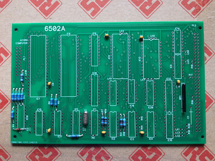
Finally after the long process of buying all the parts, well, all the electronic parts at least, construction has started 😀.
Here I have started fitting mostly some of the passive components, such as resistors and the one and only 1N4148 signal diode to the 6502A processor board.
The resistors used here are all 250mW or 600mW metal film types. A mix of 5% tolerance types (gold band) and 1% tolerance types (brown band). Most of which I keep in stock.
I normally start with the lowest profile (height) components and work my way through the various sizes finishing with the tallest last.
Progress:
Next I moved on to fitting the various 100nF ceramic "decoupling" capacitors. I normally use 100nF even if the original design lists 33nF or 47nF because I buy the 100nF in hundreds and keep in my own stock. The sightly higher value is fine. And modern multilayer ceramic types are smaller than the older disc capacitors. Most modern designs use 100nF as standard.
As I was using a low profile 24MHz crystal, that went in next. Then the resistor network (the long black thing on the right). This is eight resistors connected to a common pin.
I also fitted the 22µF axial electrolytic capacitor (on the far right of the board). I had bought two different lots, from different suppliers, as here the issue was the physical size. I selected the smaller of the two types, but it still only just fitted.
More tomorrow 😉


No comments:
Post a Comment